This board is based on the micro-controller STM32F030F4P6, so let's learn about its implementation of GPIOs.
Diving in the reference manual RM0360, I find the layout of the GPIO B registers and their initial state plus the info that peripheral clocks need to be enabled through the Reset and Clock Controller (RCC) connected on the AHB1 bus. So I need to activate the clocks of GPIO B through the RCC before I can access its registers.
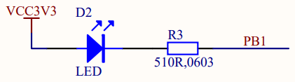
To turn the user LED on, I need to
/* Memory locations defined by linker script */
extern long __StackTop ;        /* &__StackTop points after end of stack */
void Reset_Handler( void) ;     /* Entry point for execution */

/* Interrupt vector table:
 * 1  Stack Pointer reset value
 * 15 System Exceptions
 * NN Device specific Interrupts
 */
typedef void (*isr_p)( void) ;
isr_p const isr_vector[ 2] __attribute__((section(".isr_vector"))) = {
    (isr_p) &__StackTop,
/* System Exceptions */
    Reset_Handler
} ;

#define RCC                 ((volatile long *) 0x40021000)
#define RCC_AHBENR          RCC[ 5]
#define RCC_AHBENR_IOPBEN   0x00040000  /*  18: I/O port B clock enable */

#define GPIOB               ((volatile long *) 0x48000400)
#define GPIOB_MODER         GPIOB[ 0]

void Reset_Handler( void) {
/* User LED ON */
    RCC_AHBENR |= RCC_AHBENR_IOPBEN ;   /* Enable IOPB periph */
    GPIOB_MODER |= 1 << (1 * 2) ;       /* PB1 Output [01], over default 00 */
    /* OTYPER Push-Pull by default */
    /* PB1 output default LOW at reset */
    for( ;;) ;
}
- I use the C preprocessor to specify the mapping of the peripheral
registers.
- The naming convention is from the Reference Manual, the address locations from the Data Sheet.
- Registers are indicated as volatile as they may change out of the code control, this way the compiler will avoid optimizations based on known states.
To build I just request the format I need, either .bin or .hex.
$ make ledon.hex
ledon.elf
   text    data     bss     dec     hex filename
     40       0       0      40      28 ledon.elf
ledon.hex
rm ledon.elf ledon.o
Next, I will implement the classic blinking LED.