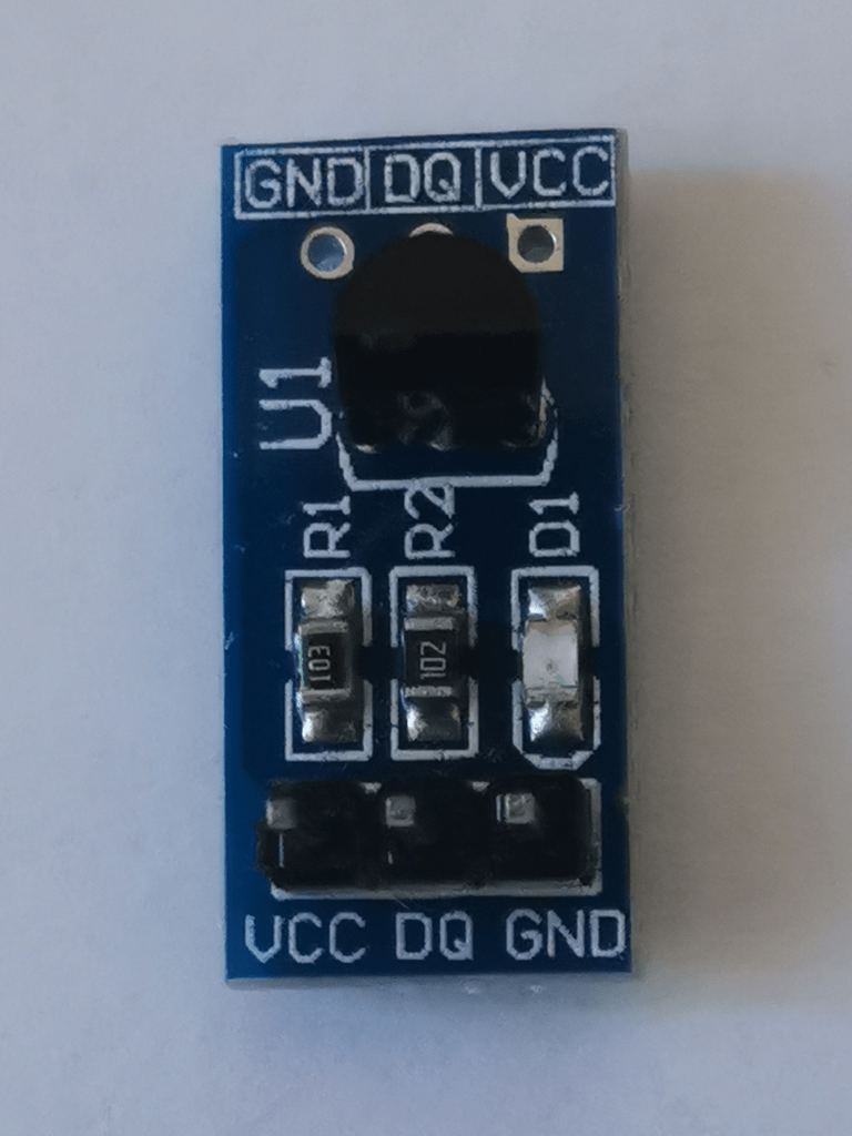
The io data line when idle need to be at high level, so a pull up resistor is necessary. The small DS18B20 board I use has a pull up resistor between vcc and io data.
A typical transaction sequence goes like this
static ds18b20_retv_t initialization() {
/* Reset */
    output() ;          /* Wire LOW */
    usleep( 480) ;
    input() ;           /* Wire floating, HIGH by pull-up */

/* Presence */
    int retries ;
    wait_level( HIGH) ; /* Pull-up LOW -> HIGH, T1 */
    wait_level( LOW) ;  /* DS18B20 asserts line to LOW, T2, T2 - T1 = 15~60us */
    wait_level( HIGH) ; /* DS18B20 releases lines, Pull-up LOW -> HIGH, T3
                        **  T3 - T2 = 60~240us */
    usleep( 405) ;      /* 480 = 405 + 15 + 60 */

    return DS18B20_SUCCESS ;
}
The ROM Command is how the host selects the device for communication.
Writing a ROM Skip command addresses all devices connected.
The Function Command is the request to the device selected by the ROM Command:
static void write( unsigned char uc) {
/* Transmit byte, least significant bit first */
    for( unsigned char curbit = 1 ; curbit ; curbit <<= 1) {
    /* Transmit a bit takes 60us + 1us between transmit */
    /* Write 1: <15us LOW */
    /* Write 0:  60us LOW */
        unsigned t = uc & curbit ? 13 : 60 ;
        output() ;      /* Wire LOW */
        usleep( t) ;
        input() ;       /* Wire floating, HIGH by pull-up */
        usleep( 61 - t) ;
    }
}
When the host expects to read some data, it can triggers a 1 bit
transmission from the device by first pulling the line LOW for 1µs then
reading the state asserted by the device.
static iolvl_t poll( void) {
    output() ;  /* Wire LOW */
    usleep( 1) ;
    input() ;   /* Wire floating, HIGH by pull-up */
    usleep( 5) ;
    iolvl_t bit = bread() ;
    usleep( 55) ;
    return bit ;
}
Integrity of the data transmitted by the device is guaranteed by 8 bit
Cyclic Redundancy Check (CRC).
static unsigned char read( unsigned char *p, int size) {
    unsigned char crc = 0 ;

    while( size--) {
    /* Receive byte, least significant bit first */
        unsigned char uc = 0 ;
        for( unsigned char curbit = 1 ; curbit ; curbit <<= 1) {
        /* read bit */
            int v = poll() ;
            if( v)
                uc |= curbit ;

        /* update CRC */
            v ^= crc ;
            crc >>= 1 ;
            if( v & 1)
                crc ^= 0x119 >> 1 ; /* reverse POLY = x^8 + x^5 + x^4 + 1 */
        }

    /* store byte */
        *p++ = uc ;
    }

    return crc ;
}
Base on this, complex transaction sequences can be coded.
The transaction to read the eight byte scratchpad (device memory) plus CRC:
static ds18b20_retv_t read_scratchpad( unsigned char scratchpad[]) {
    ds18b20_retv_t ret = initialization() ;
    if( ret != DS18B20_SUCCESS)
        return ret ;

    write( 0xCC) ;  /* Skip ROM */
    write( 0xBE) ;  /* Read Scratchpad */
    return read( scratchpad, 9) ? DS18B20_FAIL_CRC : DS18B20_SUCCESS ;
}
The host requests the conversion, waits for the conversion to end, then fetch the device memory to read the measurement.
The host can poll() the device to check if the conversion is
finished.
/* ds18b20.h -- 1-Wire temperature sensor */

typedef enum {
    DS18B20_SUCCESS,
    DS18B20_FAIL_TOUT,
    DS18B20_FAIL_CRC
} ds18b20_retv_t ;

void ds18b20_init( void) ;
ds18b20_retv_t ds18b20_resolution( unsigned res) ;  /* 9..12 bits  */
ds18b20_retv_t ds18b20_convert( void) ;
ds18b20_retv_t ds18b20_fetch( short *deciCtemp) ;/* -550~1250 = -55.0~125.0 C */
ds18b20_retv_t ds18b20_read( short *deciCtemp) ; /* -550~1250 = -55.0~125.0 C */
Usage:
ds18b20_init(), once at startup.
ds18b20_resolution() to select the resolution. It can be
done before starting a conversion. The value will be kept until the ds18b20
is powered down.
ds18b20_read(), which will
start a conversion, wait until it finishes, fetch the value from the device
memory and deci℃ (1 deci℃ = 0.1 ℃).
ds18b20_read(), call
ds18b20_convert() followed by ds18b20_fetch() once
enough time has elapsed to complete the conversion.
/* ds18b20main.c -- sample temperature using 1-Wire temperature sensor */
#include <stdio.h>
#include "system.h" /* uptime */
#include "ds18b20.h" /* ds18b20_() */
int main( void) {
unsigned last = 0 ;
ds18b20_init() ;
ds18b20_resolution( 12) ; /* Set highest resolution: 12 bits */
ds18b20_convert() ; /* start temperature conversion */
for( ;;)
if( last == uptime)
yield() ;
else {
short val ;
last = uptime ;
switch( ds18b20_fetch( &val)) {
case DS18B20_SUCCESS:
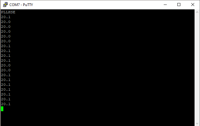
printf( "%i.%i\n", val / 10, val % 10) ;
break ;
case DS18B20_FAIL_TOUT:
puts( "Timeout") ;
break ;
case DS18B20_FAIL_CRC:
puts( "CRC Error") ;
}
ds18b20_convert() ; /* start temperature conversion */
}
}
/* ds18b20.c -- 1-Wire digital thermometer */

#include "ds18b20.h"    /* implements DS18B20 API */

#include "system.h"     /* gpioa_(), usleep() */

#define DIO 13
#define input()     gpioa_input( DIO)
#define output()    gpioa_output( DIO)
#define bread()     gpioa_read( DIO)

#define MAX_RETRIES 999
#define wait_level( lvl) \
    retries = MAX_RETRIES ; \
    while( bread() != lvl) \
        if( retries-- == 0) \
            return DS18B20_FAIL_TOUT

void ds18b20_init( void) {
    input() ;           /* Wire floating, HIGH by pull-up */
}
I add the local functions that are the building block for the
transactions (initialization(), write(),
poll() and read()) and
the read_scratchpad() transaction I explained before.
Start conversion transaction:
ds18b20_retv_t ds18b20_convert( void) {
    ds18b20_retv_t ret ;

    ret = initialization() ;
    if( ret != DS18B20_SUCCESS)
        return ret ;

    write( 0xCC) ;  /* Skip ROM */
    write( 0x44) ;  /* Convert T */
    return DS18B20_SUCCESS ;
}
Fetch temperature, to be called after conversion is done.
ds18b20_retv_t ds18b20_fetch( short *deciCtemp) { /* -550~1250 = -55.0~125.0 C $
    ds18b20_retv_t ret ;
    unsigned char vals[ 9] ;    /* scratchpad */

    ret = read_scratchpad( vals) ;
    if( ret != DS18B20_SUCCESS)
        return ret ;

    *deciCtemp = *((short *) vals) * 10 / 16 ;
    return DS18B20_SUCCESS ;
}
Blocking temperature read, which polls the device for end of conversion.
ds18b20_retv_t ds18b20_read( short *deciCtemp) { /* -550~1250 = -55.0~125.0 C */
    ds18b20_retv_t ret ;

    ret = ds18b20_convert() ;
    if( ret != DS18B20_SUCCESS)
        return ret ;

    do
        usleep( 4000) ;
    while( poll() == LOW) ; /* up to 93.75ms for 9 bits, 750ms for 12 bits */

    return ds18b20_fetch( deciCtemp) ;
}
Set resolution.
ds18b20_retv_t ds18b20_resolution( unsigned res) {  /* 9..12 bits  */
    ds18b20_retv_t ret ;
    unsigned char vals[ 9] ;    /* scratchpad */
    unsigned char curres ;

/* read scratchpad */
    ret = read_scratchpad( vals) ;
    if( ret != DS18B20_SUCCESS)
        return ret ;

/* update resolution if current value is different than requested */
    res = (res - 9) & 3 ;
    curres = vals[ 4] >> 5 ;
    if( curres != res) {
        vals[ 4] = (vals[ 4] & 0x1F) | (res << 5) ;
        ret = initialization() ;
        if( ret != DS18B20_SUCCESS)
            return ret ;

        write( 0xCC) ;  /* Skip ROM */
        write( 0x4E) ;  /* Write Scratchpad */
        write( vals[ 2]) ;
        write( vals[ 3]) ;
        write( vals[ 4]) ;
    }

    return DS18B20_SUCCESS ;
}
There is no error check when writing to the device, so it would make
sense to read back the device memory after the set to make sure there
was no error when writing in the first place.
SRCS = startup.txeie.c gpioa.c ds18b20main.c ds18b20.cBuild complete successfully.
$ make
f030f4.elf from startup.txeie.o gpioa.o ds18b20main.o ds18b20.o
   text    data     bss     dec     hex filename
   2530       0      16    2546     9f2 f030f4.elf
f030f4.hex
f030f4.bin
Flashing the board and starting execution, I can see a new output every second.