2.1: UART Validation
Before I start writing some code doing communication over the Universal Synchronous Asynchronous Receiver Transmitter (USART) peripheral, I need to validate that I have working hardware and software tools.
Board Connectivity
Even if the peripheral is capable of doing synchronous communication (that’s the S in USART), asynchronous communication (that’s the A) which only needs 3 wires (GND, TX, RX, (no clock)) is usually what is needed in non specialized cases.
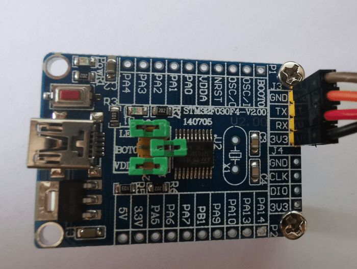
Boards sold online often have dedicated pre-soldered pins for UART connectivity similar to what we have seen before for the SWD interface. The VCC-GND board I used before doesn’t have such dedicated pins but the functionality is wired on the pins PA9 (TX) and PA10 (RX).
I will use a board with dedicated pins (GND, TX, RX, VCC 3.3V).

USB to UART adapter
An adapter is needed to connect to a PC. Either due to difference in voltage (RS232) or serial protocol (USB). Pins PA9 and PA10 are 5V tolerant, so you could interface an Arduino Uno to a STM32 board to use it as a USB to serial adapter if you happen to have a spare Arduino Uno.
I use a Waveshare PL2303 USB to UART adapter. It’s based on a Prolific PL2303TA chipset. Latest Windows USB driver for the PL2303 can be found on Prolific website. The adapter enumerates as COM4 on my Windows PC.
I configure the jumper of the adapter to provide 3.3V and make sure to cross RX and TX while connecting the adapter to the board (STM32 RX <-> Adapter TX, STM32 TX <-> Adapter RX).
STM32 Cube Programmer UART connection
So far I have been using the ST-Link interface with STM32 Cube Programmer to flash and debug. The application also support the UART interface.
Embedded Boot Loader
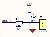
A reset of the board while jumper BOOT0 is removed will select the System memory instead of the flash memory for execution. This is where the serial flash loader protocol is implemented on chipset side.

Testing
The checklist goes like this
-
Board connected to USB adapter
-
USB driver installed on Windows PC
-
USB adapter plugged in and enumerates as a COM port
-
STM32 Cube Programmer list the COM port in device selection menu
-
BOOT0 jumper removed and board reset to start the embedded flash loader.
-
Board flash memory can be erased, written or read with the programmer.
Checkpoint
I have now working hardware and software that communicate through the serial link.
Next I will insure the code I wrote so far is working on the new board.
© 2020-2021 Renaud Fivet