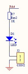
The new board uses PA4 to turn the LED ON when high. Also, by taking off a jumper, PA4 can be used for other purposes.
The first board uses PB1 to turn the LED ON when low as I have seen previously here.
I can adapt the code by adding the base address of GPIOA and shifting pin location accordingly, but this type of variations is so common that I want to make sure adaptations can be done easily without errors.
For the new board:
#define LED_IOP A
#define LED_PIN 4
#define LED_ON  1
And for the vcc-gnd board:
#define LED_IOP B
#define LED_PIN 1
#define LED_ON  0
As I have several GPIO peripheral GPIOA .. GPIOF, I switch notation,
instead of writing, say, GPIOA_MODER, I will write either
GPIOA[ MODER] or GPIO( A)[ MODER]. This way I could
refer directly to GPIO( LED_IOP)[ MODER].
I use conditional compilation based on LED_ON. If
LED_ON is high, I need an extra step during initialization
compare to LED_ON low. On the other hand, if LED_ON
is undefined, the code would be removed for a board that doesn't have a user
LED.
#define SYSTICK             ((volatile long *) 0xE000E010)
#define SYSTICK_CSR         SYSTICK[ 0]
#define SYSTICK_RVR         SYSTICK[ 1]
#define SYSTICK_CVR         SYSTICK[ 2]

#define CAT( a, b) a##b
#define HEXA( a) CAT( 0x, a)
#define RCC                 ((volatile long *) 0x40021000)
#define RCC_AHBENR          RCC[ 5]
#define RCC_AHBENR_IOP( h)  (1 << (17 + HEXA( h) - 0xA))

#define GPIOA               ((volatile long *) 0x48000000)
#define GPIOB               ((volatile long *) 0x48000400)
#define GPIO( x) CAT( GPIO, x)
#define MODER   0
#define ODR     5

/* user LED ON when PA4 is high */
#define LED_IOP A
#define LED_PIN 4
#define LED_ON  1

void SysTick_Handler( void) {
#ifdef LED_ON
    GPIO( LED_IOP)[ ODR] ^= 1 << LED_PIN ;   /* Toggle User LED */
#endif
}

int init( void) {
/* By default SYSCLK == HSI [8MHZ] */

/* SYSTICK */
    SYSTICK_RVR = 1000000 - 1 ;     /* HBA / 8 */
    SYSTICK_CVR = 0 ;
    SYSTICK_CSR = 3 ;               /* HBA / 8, Interrupt ON, Enable */
    /* SysTick_Handler will execute every 1s from now on */

#ifdef LED_ON
/* User LED ON */
    RCC_AHBENR |= RCC_AHBENR_IOP( LED_IOP) ;        /* Enable IOPx periph */
    GPIO( LED_IOP)[ MODER] |= 1 << (LED_PIN * 2) ;  /* LED_IO Output [01],
                                                    ** over default 00 */
    /* OTYPER Push-Pull by default */
    /* Pxn output default LOW at reset */
# if LED_ON
    SysTick_Handler() ;
# endif
#endif
    return 0 ;
}
SRCS definition in Makefile.
SRCS = startup.c board.c success.cand build.
$ make
f030f4.elf
   text    data     bss     dec     hex filename
    224       0       0     224      e0 f030f4.elf
f030f4.hex
f030f4.bin
Once I have flashed the board with this new binary, I put back the BOOT0
jumper and press reset. This board user LED is red. 😎
Next, I will do some serial transmission.